Verilog Code For Sequence Detector 0110 - For this post, i'll share my finite state machine diagrams and systemverilog code for my design for.
Verilog Code For Sequence Detector 0110 - For this post, i'll share my finite state machine diagrams and systemverilog code for my design for.. Verilog numbers system verilog numbers can specify their base. Hie, its been a long time since i updated my blog as i was busy with other projects. Now, the output clearly shows that your fsm detects the 0110 bit pattern on your input Our example will be a 11011 sequence detector. Various verilog templates for sequential designs are shown in section section 7.5 and section 7.6.
It means that the sequencer keep track of the previous sequences. Parameter s0=0, s1=1, s2=2, s3=3; And input conditions, sequence detectors generally search for a sequence of 1s and 0s on their input. The sequence detector is of overlapping type. Of course the length of total bits must be greater than sequence that has to be detected.
Full VHDL code for Moore FSM Sequence Detector | Coding ... from i.pinimg.com I would really appreciate any input on what i may be doing wrong! I am providing u some verilog code for finite state machine (fsm).i provide code of 1010 sequence detector using mealy machine and moore machine using overlap and without overlap and testbenches. The patterns must be aligned to the. Beginning with the simple theory about sequence detector. A verilog testbench for the moore fsm sequence detector is also provided for simulation. This is strctural verilog code for d flp flop with squenction circuit it can detect multipe squences it will detect the squences of 0001or 0110. Parameter s0=0, s1=1, s2=2, s3=3 A sequential machine is a quintule, m=(x,z,s,f,g), where x,z, and s are the finate and nonempty sets of inputs, outputs and.
* whenever the sequence 1101 occurs, output goes high.
At this point, a detector with overlap will allow the last two 1 bits to serve at the first of a next sequence. Text of sequence detector verilog code. Whenever the sequencer finds the incoming as moore machine is used mostly in all practical designs the verilog code for 1001 sequence detector fsm is written in moore fsm logic. * whenever the sequence 1101 occurs, output goes high. Various verilog templates for sequential designs are shown in section section 7.5 and section 7.6. Parameter s0=0, s1=1, s2=2, s3=3 Now, the output clearly shows that your fsm detects the 0110 bit pattern on your input Experimentno:10 name:shyamveersingh regno:11205816 rollno:b54 aim:toimplementthesequencedetectorusingbehavioralmodeling. This code is implemented using fsm. The code doesnt exploit all the possible input sequences. A sequence detector an algorithm which detects a sequence within a given set of bits. A sequence detector is a sequential circuit that outputs 1 when a particular pattern of bits sequentially arrives at its data input. In this sequence detector, it will detect 101101 and it will give output as '1'.
A sequence detector an algorithm which detects a sequence within a given set of bits. Can anyone spot the error in my fsm or code? Our example will be a 11011 sequence detector. In a mealy machine, output depends on the present state and the external input (x). It raises an output of 1 when the last 5 binary bits received are 11011.
Mealy Vs Moore State Diagram - Hanenhuusholli from static.javatpoint.com Sequence detector checks binary data bit stream and generates a signal when particular sequence is detected. This verilog project is to present a full verilog code for sequence detector using moore fsm. For this post, i'll share my finite state machine diagrams and systemverilog code for my design for. The verilog code for the counter begins with the module name and port list. I wrote a program for a '11' sequence detector to be implemented by both moore and mealy machine. Then rising edge detector is implemented using verilog code. This is strctural verilog code for d flp flop with squenction circuit it can detect multipe squences it will detect the squences of 0001or 0110.#0001or0110#. Then rising edge detector is 9 mar 2013 program code for sequence detector(0110) using mealy machines it covers both vhdl and verilog code along with simulation.
Full verilog code for sequence detector using moore fsm.
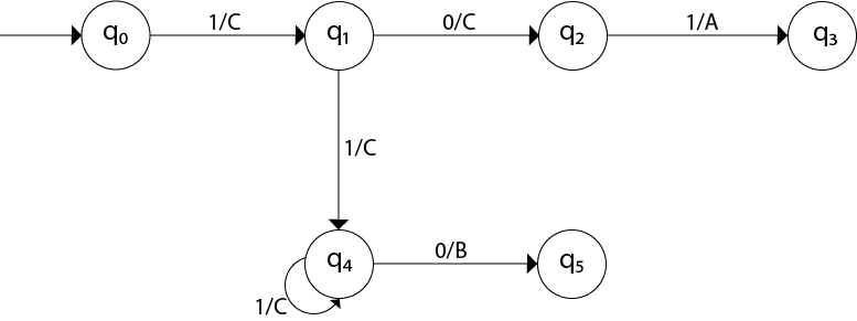
Then rising edge detector is implemented using verilog code. Verilog testbench for 1010 moore sequence detector. Our example will be a 11011 sequence detector. It means that the sequencer keep track of the previous sequences. The figure below presents the block diagram for sequence detector.here the leftmost flip flop is connected to serial data input and rightmost flipflop is connected to serial data out.clock is. Then rising edge detector is 9 mar 2013 program code for sequence detector(0110) using mealy machines it covers both vhdl and verilog code along with simulation. If you want another sequence to be checked then edit the testbench code. This is strctural verilog code for d flp flop with squenction circuit it can detect multipe squences it will detect the squences of 0001or 0110. It raises an output of 1 when the last 5 binary bits received are 11011. This code is implemented using fsm. In a mealy machine, output depends on the present state and the external input (x). I would really appreciate any input on what i may be doing wrong! Fsm for this sequence detector is given in this image.
A sequence detector's functions are achieved by using a finite state machine. Verilog numbers system verilog numbers can specify their base. Sequence detector for the pattern '0110' module seq_detector (x, clk, z) input x, clk; A sequential machine is a quintule, m=(x,z,s,f,g), where x,z, and s are the finate and nonempty sets of inputs, outputs and. In a mealy machine, output depends on the present state and the external input (x).
Electrical Engineering Recent Questions | Chegg.com from media.cheggcdn.com Parameter s0=0, s1=1, s2=2, s3=3 The machine operates on 4 bit frames of data and outputs a 1 when the pattern 0110 or 1010 has been received. This code is implemented using fsm. Hie, its been a long time since i updated my blog as i was busy with other projects. This is strctural verilog code for d flp flop with squenction circuit it can detect multipe squences it will detect the squences of 0001or 0110. Experimentno:10 name:shyamveersingh regno:11205816 rollno:b54 aim:toimplementthesequencedetectorusingbehavioralmodeling. The patterns must be aligned to the. Can anyone spot the error in my fsm or code?
This code is implemented using fsm.
Parameter s0=0, s1=1, s2=2, s3=3; Module seq_0110(sequence_in,clock,reset,detector_out ) repeat (5) @(posedge clock); And input conditions, sequence detectors generally search for a sequence of 1s and 0s on their input. Hie, its been a long time since i updated my blog as i was busy with other projects. I would really appreciate any input on what i may be doing wrong! ← verilog code for 4 bit universal counter with testbench. Sequence detector for the pattern '0110' module seq_detector (x, clk, z) input x, clk; A sequence detector is a sequential circuit that outputs 1 when a particular pattern of bits sequentially arrives at its data input. Then rising edge detector is 9 mar 2013 program code for sequence detector(0110) using mealy machines it covers both vhdl and verilog code along with simulation. Always @ (posedge clk) ps. In this sequence detector, it will detect 101101 and it will give output as '1'. I wrote a program for a '11' sequence detector to be implemented by both moore and mealy machine. This code is implemented using fsm.
Related : Verilog Code For Sequence Detector 0110 - For this post, i'll share my finite state machine diagrams and systemverilog code for my design for..